
Precautions for Using a Frequency Converter
1. Characteristics of Frequency Converters
- A frequency converter is an electrical energy control device that uses semiconductor components to switch on and off, converting fixed-frequency AC power into continuously adjustable frequency AC power.
- A general-purpose frequency converter is one that can be used with standard cage-type asynchronous motors, adaptable to various load characteristics, and offers a variety of selectable functions. General-purpose frequency converters are mainly used in applications like pumps and fans, where precise speed control is not crucial.
2. Classification of Frequency Converters
- By Operating Principle: They can be divided into AC-AC converters and AC-DC-AC converters.
- By Control Method: They include V/f control converters, slip frequency control converters, vector control converters, and direct torque control converters.
- By Energy Storage in the DC Link: There are current-source inverters and voltage-source inverters.
- By Supply Voltage Level: Frequency converters can be categorized as low-voltage, medium-voltage, and high-voltage converters.
3. Basic Control Functions of Frequency Converters
- The correct method for external forward rotation control in a frequency converter is that the contactor (KM) only controls the power supply to the converter, while the motor’s start/stop is controlled by the relay (KA) via the forward rotation terminal “FWD” and the common terminal “COM.” KM should close before KA can close, and KA should open before KM opens, with interlocking between KM and KA.
- If the converter uses a power-on start control method, issues like non-operation or inaccurate motor stopping can occur, potentially causing interference with the power supply.
- If the converter is preset to operate via a keypad, it can be controlled directly after powering on, including starting, stopping, jogging, and resetting. Whether the “STOP” button on the keypad is effective during external control depends on the specific user settings.
- Changing the motor’s rotation direction directly through external terminals can cause “reverse braking,” resulting in large surge currents. To prevent this, a dead zone control can be set at zero speed.
4. External Connection Terminals of the Frequency Converter
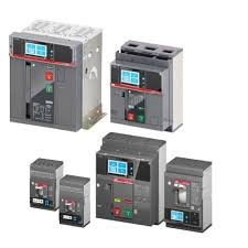
- The external output control terminals of the frequency converter include alarm output terminals, measurement signal output terminals, communication interfaces, and status signal output terminals. Terminals 30A, 30B, and 30C serve as alarm output terminals; the input terminals R, S, T connect to the power supply, and the output terminals U, V, W connect to the motor. The input and output terminals must not be connected incorrectly, as this could cause a power short-circuit fault.
- Various frequency converters come equipped with terminals for receiving externally inputted set signals, typically including voltage and current signal set terminals. The external input control terminals of the converter receive switching signals, which are then processed internally by optocouplers.
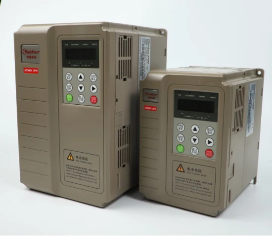
5. Control Panel of the Frequency Converter
- In monitoring mode, the frequency converter displays various operational data; in operation mode, it displays function codes and data codes; and in fault mode, it shows fault cause codes. The display screen shows function codes and data codes during presetting and fault codes during errors.
- Upon powering on, the frequency converter first enters operation mode. The data increment and decrement keys are used to adjust values, search for function codes in programming mode, and modify data codes; in operation mode, these keys adjust the output frequency. To switch from operation mode to programming mode, the mode switch key must be pressed. The data increment key symbol is “▲,” and the jog control symbol is “JOG.”
6. Installation and Commissioning of the Frequency Converter
- Before using the converter, familiarize yourself with the keypad and display content switching, and perform function presetting. After powering on, observe the display process, check the operation of the internal fan, and measure the three-phase input voltage for abnormalities.
- Connect the motor and load for a test run. If the motor does not quickly rotate at low frequencies, indicating difficulty in starting, increase the start frequency appropriately. Adjust the frequency to the maximum set value so that the motor accelerates to its maximum speed according to the preset acceleration time. If there is a trip due to excessive current, extend the acceleration time.
- The load-bearing capacity test of the converter involves running the motor at the minimum speed required by the load with the rated load for an extended period, observing the motor’s heating condition.
- During shutdown testing, switch the display to show DC voltage and monitor whether the DC voltage is too high during deceleration.
- A frequency converter with vector control capability automatically measures the motor parameters during a no-load operation.
7. Control Circuit of the Frequency Converter
The control circuit, which provides on/off control signals to the converter’s main circuit, has the primary tasks of controlling the switching of inverter components and providing multiple protection functions. The control circuit of the converter consists of an arithmetic circuit, signal detection circuit, drive circuit, and protection circuit.
Continuous Operation Control Circuit for Frequency Regulation
As shown in the diagram, the input terminals R, S, T of the frequency converter are connected to a three-phase power supply via an AC contactor, and the output terminals U, V, W are connected to a three-phase asynchronous motor. The motor can only run forward when the AC contactor’s main contact is closed, and the main control circuit sends a forward operation signal (i.e., FWD and COM are connected).

If the FWD and COM terminals of the frequency converter are shorted, the converter can run forward as long as the R, S, and T terminals are connected to a three-phase power supply. However, this method is generally not recommended due to potential issues with accuracy and reliability, as the inrush current at the moment the power is connected can interfere with the power grid. For improved accuracy and reliability, forward control usually involves using the normally open contact of an intermediate relay to connect FWD and COM, while the main contact of the AC contactor connects the three-phase power supply.
Forward and Reverse Rotation Control Circuit for Frequency Regulation

As shown in the diagram, when controlling the motor’s forward and reverse rotation using a frequency converter, the AC contactor connects the converter’s power supply, and two intermediate relays connect the forward and reverse control signals. The control of the AC contactor and the two intermediate relays must ensure sequential start-up and reverse order shutdown. To implement forward and reverse control with a frequency converter, the normally closed contacts of the intermediate relays must provide interlock protection.