Complete Explanation of Circuit Breakers

Classification of Circuit Breakers
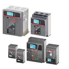
(1) Air Circuit Breaker (ACB)
Air circuit breakers, also known as universal circuit breakers, house all components within an insulated metal frame. They are typically open-type and can be equipped with various accessories. The contacts and parts are easy to replace, making them ideal as main switches at power supply terminals. Overcurrent trip units can be electromagnetic, electronic, or intelligent. ACBs provide four levels of protection: long delay, short delay, instantaneous, and ground fault. Each protection setting can be adjusted within a certain range according to its frame level.
Air circuit breakers are suitable for distribution networks with AC 50Hz, rated voltage 380V, 660V, and rated current from 200A to 6300A. They are mainly used to distribute electrical energy and protect circuits and power equipment from overload, undervoltage, short circuit, and single-phase ground faults. These breakers have multiple intelligent protection functions for selective protection. Under normal conditions, they can be used for infrequent switching of lines. Breakers rated below 1250A can be used to protect motors from overload and short circuit in AC 50Hz, 380V networks.
Air circuit breakers are also commonly used as main switches on the 400V side of transformers, bus tie switches, large capacity feeder switches, and large motor control switches.
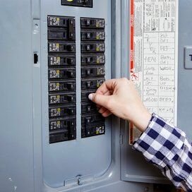
(2) Molded Case Circuit Breaker (MCCB)
Molded case circuit breakers, also known as device circuit breakers, encapsulate terminals, arc extinguishers, trip units, and operating mechanisms within a plastic case. Auxiliary contacts, undervoltage trip units, and shunt trip units are often modularized, creating a very compact structure. Typically, MCCBs are not considered for maintenance and are used as branch protection switches. They usually contain thermal-magnetic trip units, while larger MCCBs may have solid-state trip sensors.
MCCB overcurrent trip units come in electromagnetic and electronic types. Generally, electromagnetic MCCBs are non-selective and offer only long delay and instantaneous protection. Electronic MCCBs provide long delay, short delay, instantaneous, and ground fault protection. Some new electronic MCCBs also feature zone selective interlocking.
MCCBs are mainly used for distribution feeder control and protection, as the main switch on the low-voltage side of small distribution transformers, power distribution terminal control, and as power switches for various production machinery.
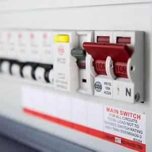
(3) Miniature Circuit Breaker (MCB)
Miniature circuit breakers are the most widely used terminal protection devices in building electrical systems. They protect against short circuit, overload, and overvoltage for single-phase or three-phase circuits below 125A, including single-pole (1P), two-pole (2P), three-pole (3P), and four-pole (4P) configurations.

MCBs consist of operating mechanisms, contacts, protection devices (various trip units), and arc extinguishing systems. The main contacts can be manually or electrically operated. After the main contacts close, a free trip mechanism locks them in the closed position. The overcurrent trip coil and thermal trip elements are in series with the main circuit, and the undervoltage trip coil is in parallel with the power supply.
In civil building electrical design, MCBs are mainly used for overcurrent, short circuit, overvoltage, undervoltage, grounding, leakage, dual power automatic switching, and infrequent motor start-up protection.
Basic Parameters of Circuit Breakers
(1) Rated Operating Voltage (Ue)
The rated operating voltage is the nominal voltage at which the circuit breaker can operate continuously under specified normal use and performance conditions.
For voltage levels at or below 220kV in China, the maximum operating voltage is 1.15 times the system rated voltage; for levels at or above 330kV, it is 1.1 times the rated voltage. Circuit breakers must maintain insulation and operate according to specified conditions at the system’s maximum operating voltage.
(2) Rated Current (In)
The rated current is the maximum current that the trip unit can continuously pass under an ambient temperature below 40°C. For breakers with adjustable trip units, it is the maximum current that can pass through the trip unit for an extended period.
When used in environments exceeding 40°C but not higher than 60°C, the load should be reduced for long-term operation.
(3) Overload Trip Current Setting (Ir)
The circuit breaker will trip after a delay if the current exceeds the trip current setting (Ir). This setting must be higher than the maximum load current (Ib) but lower than the maximum allowable current of the circuit (Iz).
Thermal trip relays can generally be adjusted within 0.7 to 1.0 times the rated current (In). If electronic devices are used, the adjustment range is typically 0.4 to 1.0 times In. For breakers with non-adjustable overcurrent trip units, Ir equals In.
(4) Short-Circuit Trip Current Setting (Im)
The short-circuit trip relay (instantaneous or short delay) quickly trips the breaker at high fault current values, with a tripping threshold of Im.
(5) Rated Short-Time Withstand Current (Icw)
This is the maximum current that can pass through the breaker for a specified time without damaging the conductors due to overheating.
(6) Breaking Capacity
The breaking capacity of a circuit breaker is its ability to safely interrupt fault currents. This capacity is independent of its rated current and is typically specified in ranges like 36kA or 50kA. It is divided into ultimate short-circuit breaking capacity (Icu) and service short-circuit breaking capacity (Ics).
General Principles for Selecting Circuit Breakers
- Choose the type and poles of the breaker according to its application.
- Select the rated current based on the maximum working current.
- Choose the type of trip unit, accessories, and specifications as needed.
Specific requirements include:
- The breaker’s rated operating voltage should be ≥ the circuit’s rated voltage.
- The breaker’s rated short-circuit breaking capacity should be ≥ the circuit’s calculated load current.
- The breaker’s rated short-circuit breaking capacity should be ≥ the maximum short-circuit current that may occur in the circuit (usually calculated in RMS).
- The single-phase ground fault current at the end of the circuit should be ≥ 1.25 times the instantaneous (or short delay) trip current setting of the breaker.
- The undervoltage trip unit’s rated voltage should equal the circuit’s rated voltage.
- The shunt trip unit’s rated voltage should equal the control power supply voltage.
- The rated operating voltage of the motor drive mechanism should equal the control power supply voltage.
- When used for lighting circuits, the instantaneous trip current of the electromagnetic trip unit is generally set at six times the load current.
- When protecting a single motor from short circuits, the instantaneous trip current is set at 1.35 times (DW series breakers) or 1.7 times (DZ series breakers) the motor start-up current.
- When protecting multiple motors from short circuits, the instantaneous trip current is set at 1.3 times the largest motor’s start-up current plus the working current of the remaining motors.
- When used as the main switch on the low-voltage side of a distribution transformer, the breaker’s breaking capacity should exceed the short-circuit current on the transformer’s low-voltage side. The trip unit’s rated current should not be less than the transformer’s rated current. The short-circuit protection setting is generally 6-10 times the transformer’s rated current, and the overload protection setting equals the transformer’s rated current.
- After preliminarily selecting the type and level of the breaker, ensure coordination with the protection characteristics of upstream and downstream switches to prevent cascading tripping and expanding accident scope.
Selectivity of Circuit Breakers
In distribution systems, circuit breakers are classified by protection performance into selective and non-selective types. Selective low-voltage breakers provide two-stage and three-stage protection. Instantaneous and short delay characteristics are suitable for short-circuit actions, while long delay characteristics are for overload protection. Non-selective breakers typically act instantaneously, offering only short-circuit protection. In some cases, long delay action is used only for overload protection.
To achieve selectivity, the upstream breaker may be selective while the downstream breaker can be non-selective or selective. Utilizing the delay action of the short delay trip unit or different delay times helps achieve selectivity. When configuring the delay action of the upstream breaker, consider the following:
- The instantaneous overcurrent trip setting of the upstream breaker should not be less than 1.1 times the maximum three-phase short-circuit current at the downstream breaker’s terminal.
- If the downstream breaker is non-selective, to prevent the upstream short delay trip unit from tripping first due to insufficient sensitivity, the upstream breaker’s short delay trip unit setting should be at least 1.2 times the downstream instantaneous trip setting.
- If the downstream breaker is also selective, the upstream breaker’s short delay action time should be at least 0.1s longer than the downstream breaker’s short delay action time. To ensure selective action between two levels of low-voltage breakers, the upstream breaker should have a short delay overcurrent trip unit, and its action current should be one level higher than the downstream trip unit, at least 1.2 times the downstream action current (Iop.1 ≥ 1.2Iop.2).
Cascading Protection of Circuit Breakers
In designing distribution systems, the coordination between upstream and downstream circuit breakers must ensure selectivity, speed, and sensitivity.
Selectivity relates to the coordination between breakers, while speed and sensitivity depend on the characteristics of the protective devices and the operation mode of the circuit.
Proper coordination ensures that only the faulty section is isolated, preventing unnecessary power outages and reducing accident impacts.